Building my first keyboard
Do you like LEGO? Do you like mechanical keyboards? Have you ever thought “My keyboard has too many keys”? This is the story of how I built the first mechanical keyboard I have ever owned.
When I first started studying programming, I told myself, ‘When I get my first real programming job, I’ll buy a cool mechanical keyboard.’. I suppose I spent far too many hours scrolling through Reddit. Time flew by and, before I knew it, I was a developer with years of experience—but I had not yet fulfilled that promise to myself. On top of that, I always wanted to try mechanical keyboards but never found one in the wild. After discovering Cheapino, I knew I had to pull the trigger and build one.
The Cheapino buying guide is amazing. A massive shout-out to Tompi for putting it together.I ordered everything from AliExpress and the PCB from JLCPCB without fuss.I felt confident enough to tackle the project despite having no prior experience. I didn’t even have an Aliexpress account before this.
It took a while but everything got here. Thankfully, a friend who tinkers with electronics already had all the necessary tools, so we got to work.
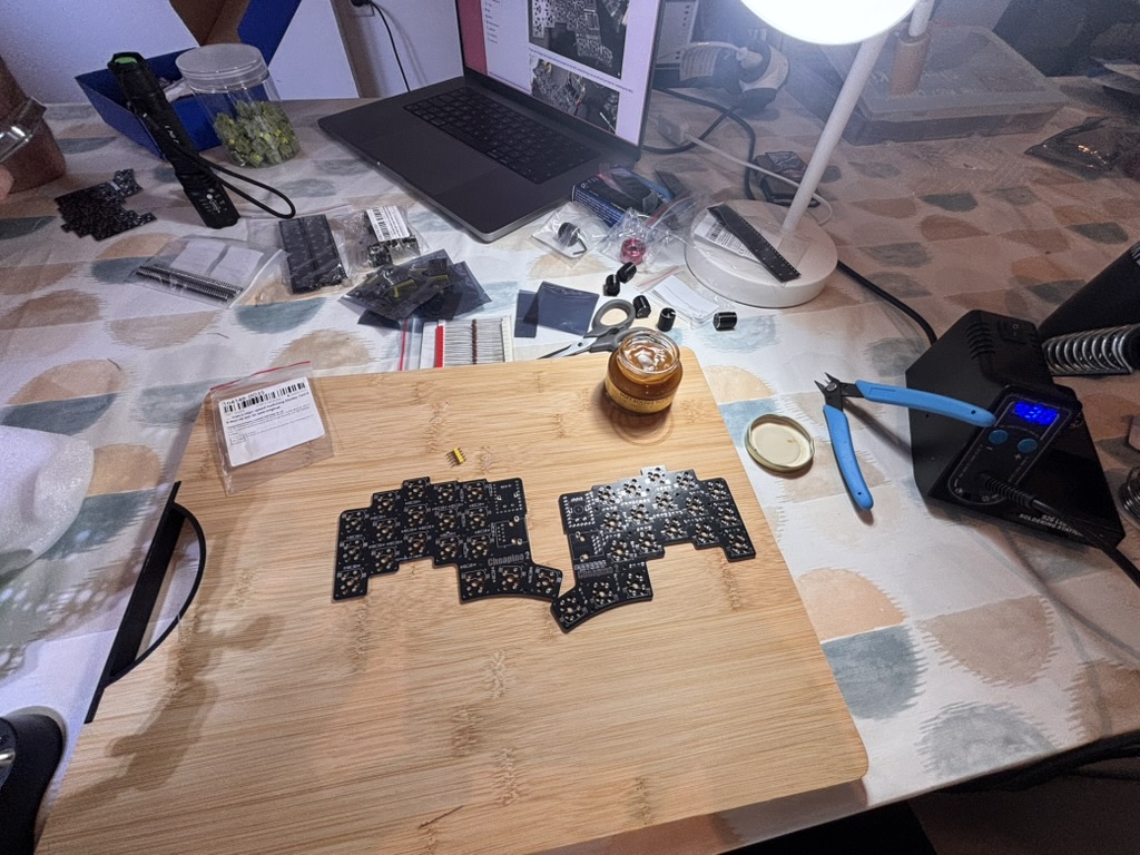
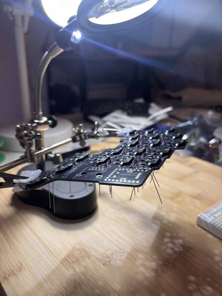
I used a cutting board, so I wouldn’t accidentally burn my dinner table. That was pretty smart, as I ended up burning the back of the cutting board a few times. First thing I did was solder all the sockets. It seemed the most straightforward thing to do, as I could lay the PCB flat.
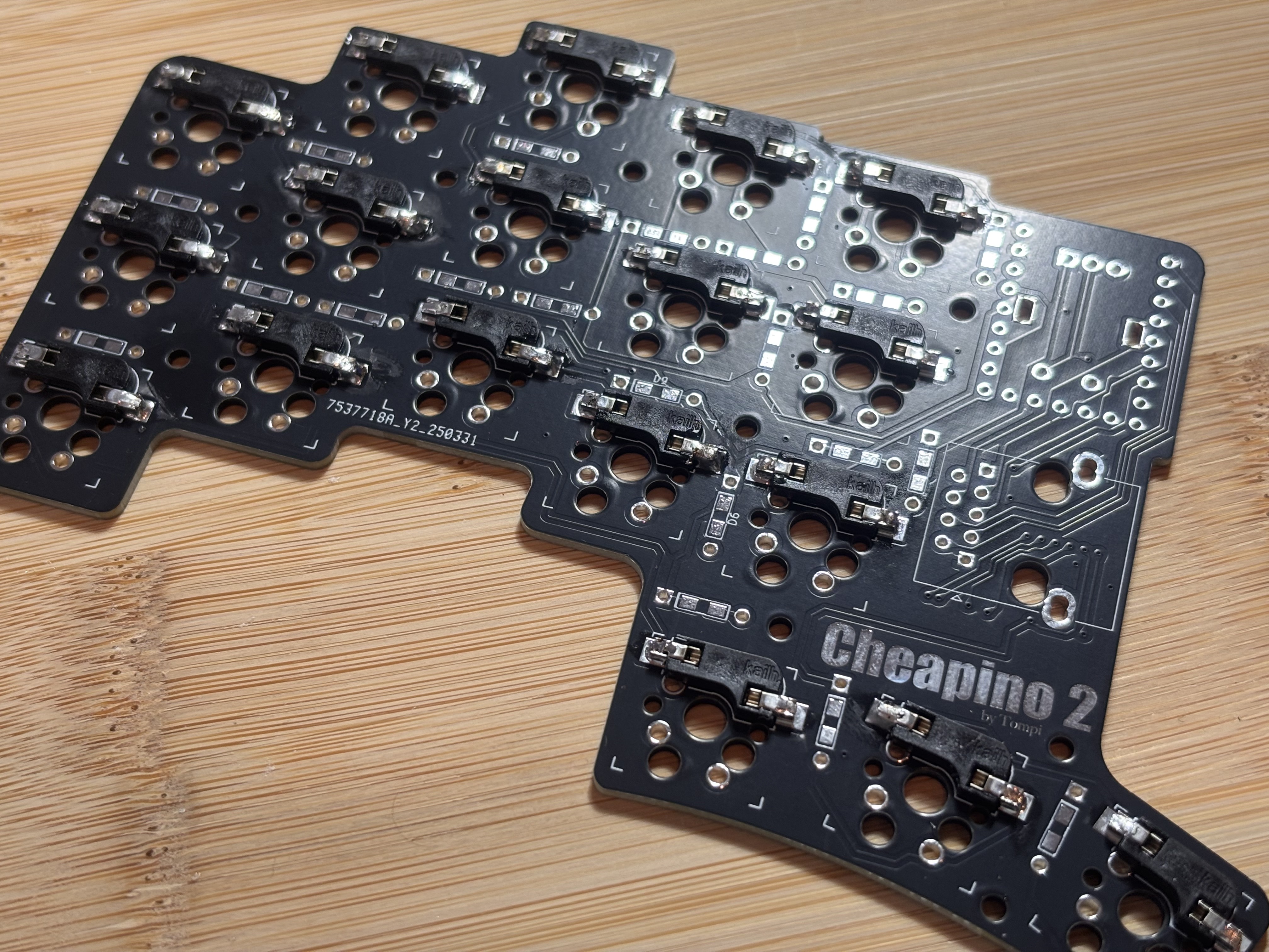
Here’s the final result. I really don’t know if I did a good job soldering the sockets but almost all of them worked on the first try. Job done!
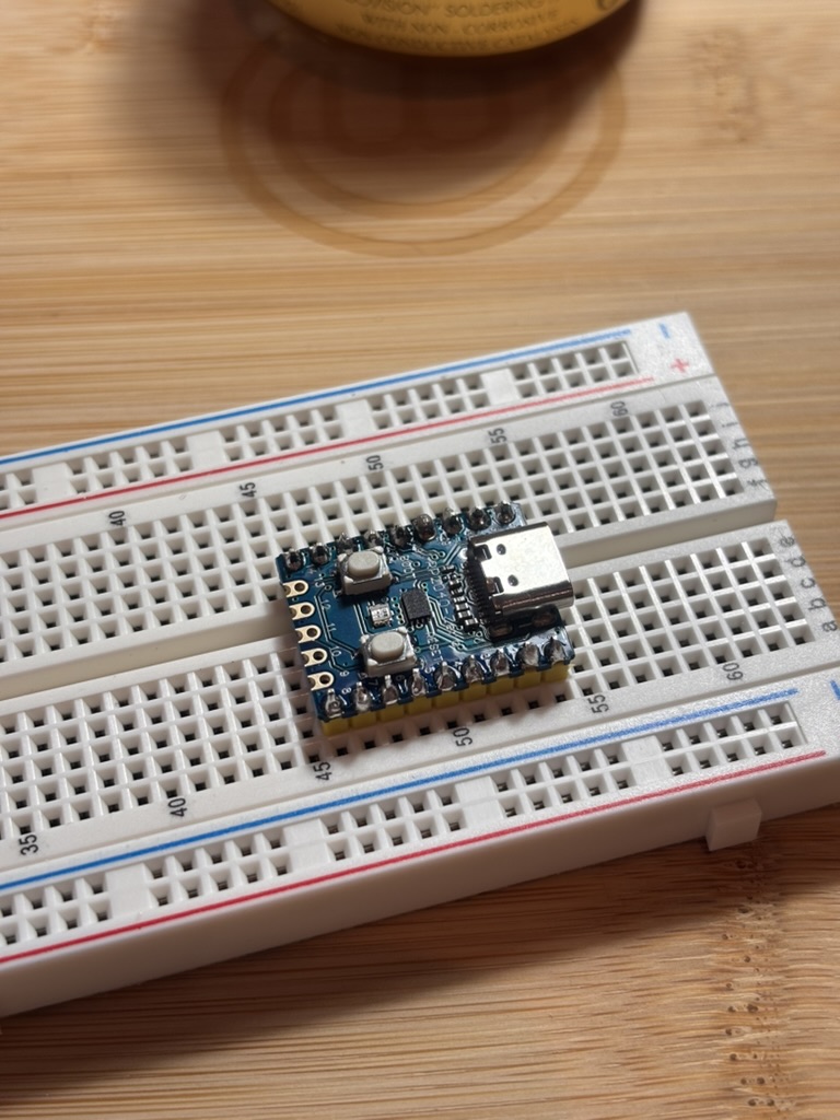
The MCU came with its own pin sockets. They were really thick so it was easy to solder them everywhere. This would come back to haunt me later, but for now everything was going smoothly. I felt as though I were building a LEGO set.
Here I was soldering the diodes. This part was tricky at first, but after doing one PCB I learnt how to go quickly and correctly.
You can solder the diodes from the top or from the bottom. I think that soldering from the top is easier, as you don’t need to bend the diode’s legs to turn them upside down. Also, gravity is unstoppable. The diodes would always move or fall whenever I was trying to solder them to the PCB from the bottom.
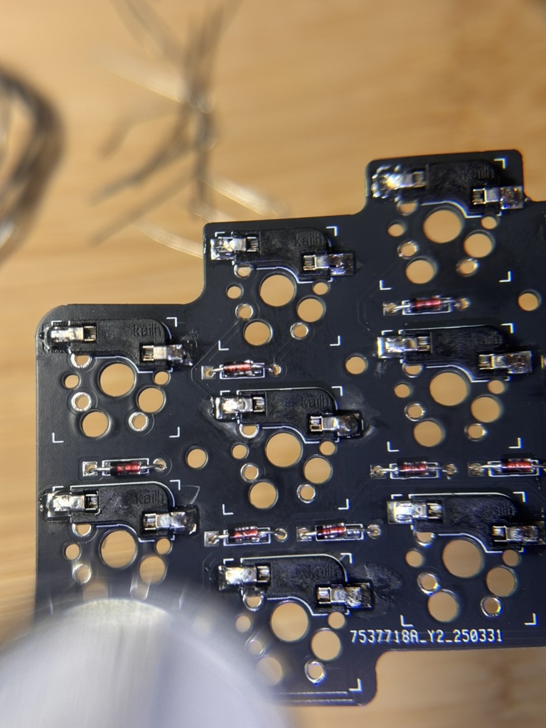
Here you can see the diodes put into place. They are those tiny red things with a black band, which must go into the square diode hole. I missed a few diodes and even soldered some on the wrong side, so I had to redo them. Plenty of beginner errors, but nothing that ruined the build!
You can also see in the picture that soldering from the top works perfectly well. The opening is not that big and the final look is better because you’re not fighting gravity.
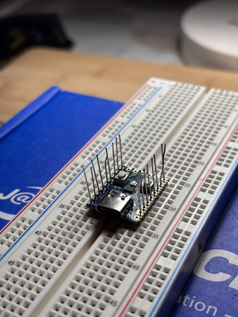
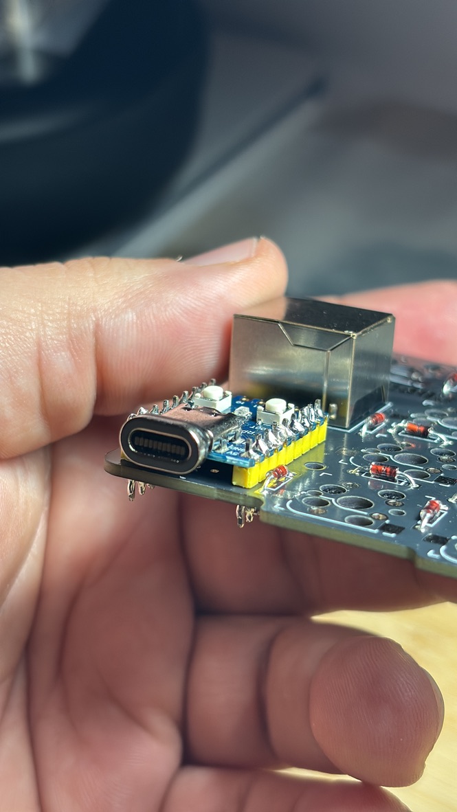
One note: the Cheapino guide recommends using sockets for the MCU so you can remove it later. The pins that came with the MCU were too thick to fit inside the sockets, so I had to reuse the legs I cut from the diodes.
That was not a nice experience.
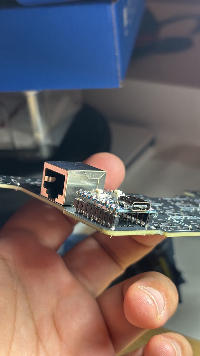
As you can see on the picture above, the socket is really tall and stands out a lot. Also, when soldering the diode legs into the MCU, you have to be careful with the heights of the legs, as they can individually move around.
I couldn’t buy just one MCU-I had to buy 5. I don’t see the point of having this socket on the board. You can see the image below, the MCU with the included pins soldered directly into the board looks way better. On top of that, I mistakenly cut some diode legs too short after soldering them into the MCU and if I move the keyboard too much I need to push it down a little bit so every key works properly again.
In a few hours, ta-da!! I had my keyboard fulling working. Installing the RJ45 sockets was really simple-just aligning them correctly. I installed some of my Outemu silent tactile switches and plugged it in while holding the ‘boot’ button on the MCU. I moved the necessary firmware file onto it, and the keyboard was working.
Well, almost working. I had missed some diodes and some were on the wrong side. Nothing major, I could fix everything by myself, just looking at the PCB. A few hot-swap sockets needed extra attention, but that was easier after I watched a YouTube video on soldering them properly.
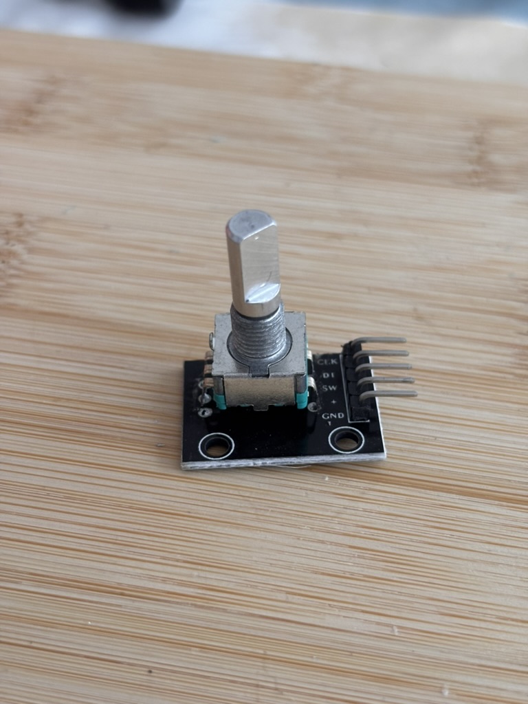
After I got all the keys working, I fitted the keycaps and went to work! You can see I was missing the potentiometer there, I had to buy one the next day from a local shop because I’d forgotten to order it from AliExpress.
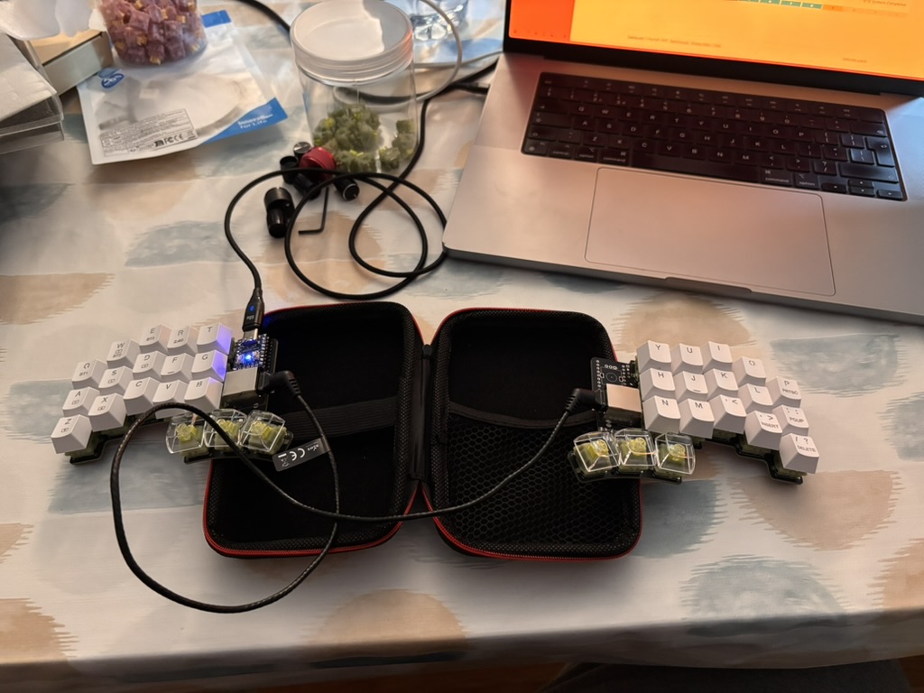
My local shop only had this thing here that is used in Arduino boards. I just heated all the feets with the soldering iron and removed it. After that, it was easy to put it into my board.
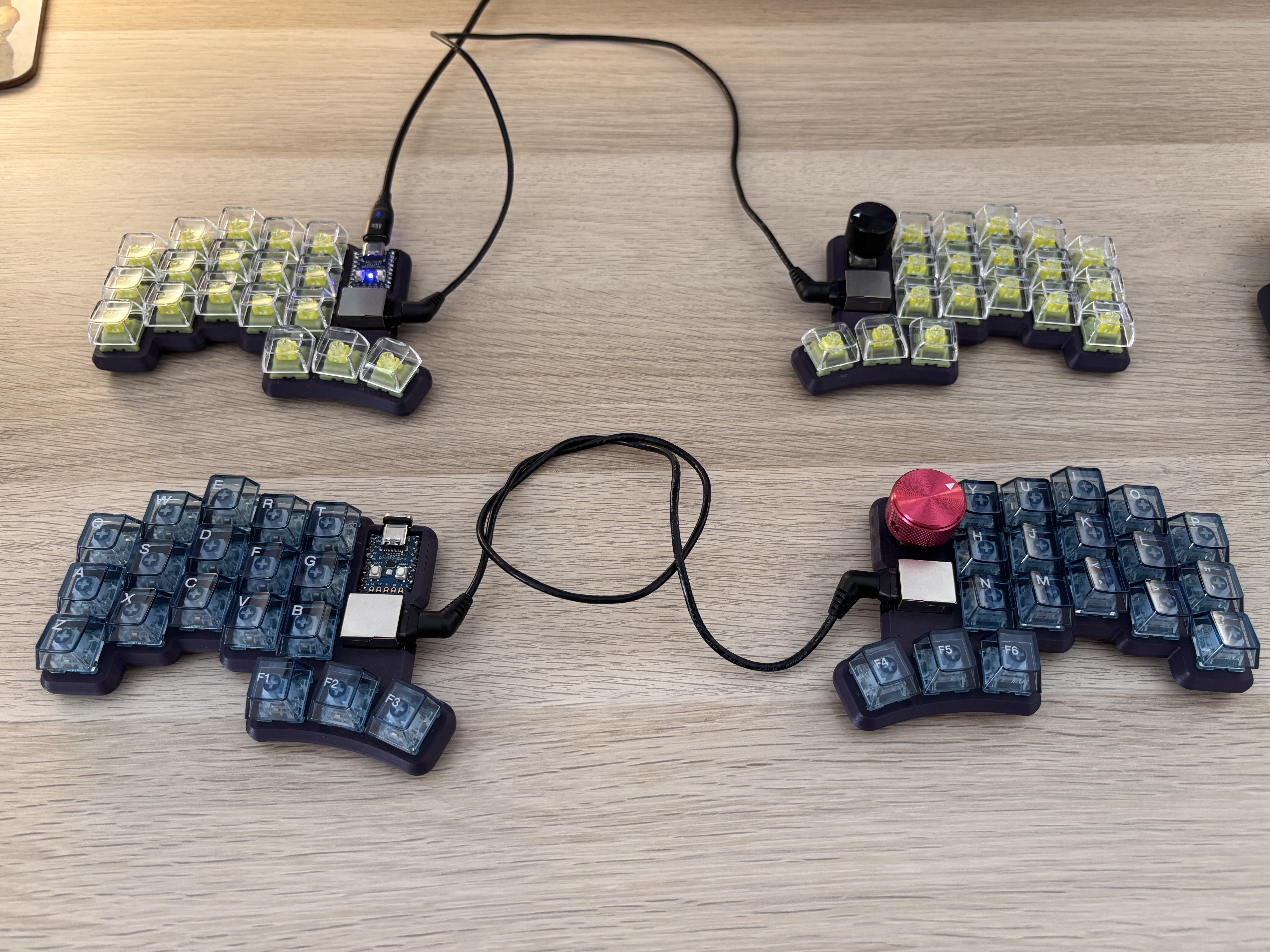
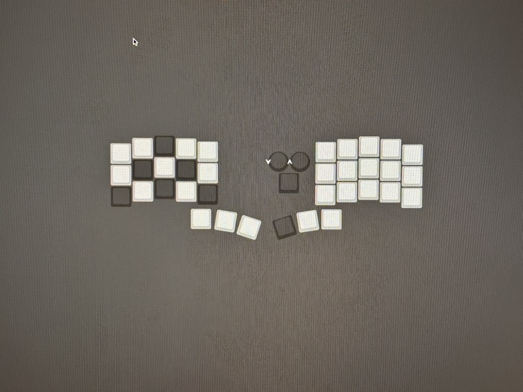
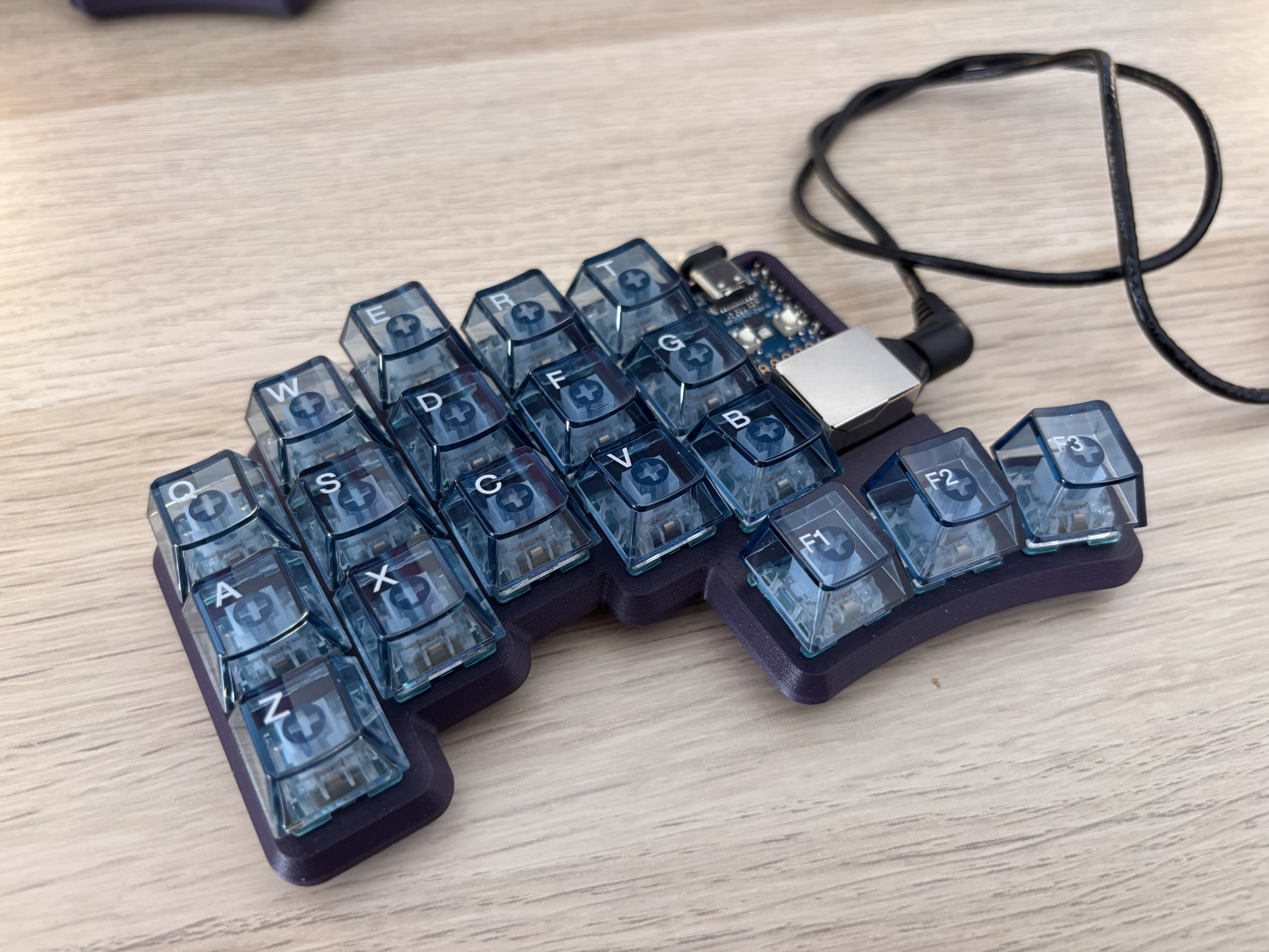
Here’s the final result:
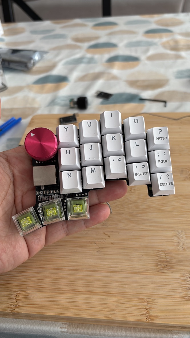
It looks pretty cool!! I was really happy with it. I had to use some printed keycaps at first because I had never used ortholinear keyboards before, and I was getting really lost, especially on the bottom row.
My friend who loves electronics, also loves 3D printing so he hooked me up with a purple case. I think the keyboard looks awesome with the colour palette and the transparent keycaps.
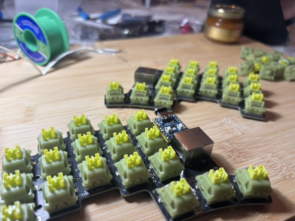
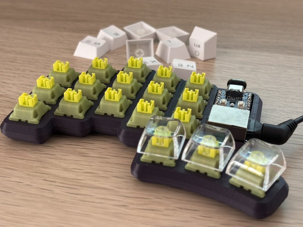
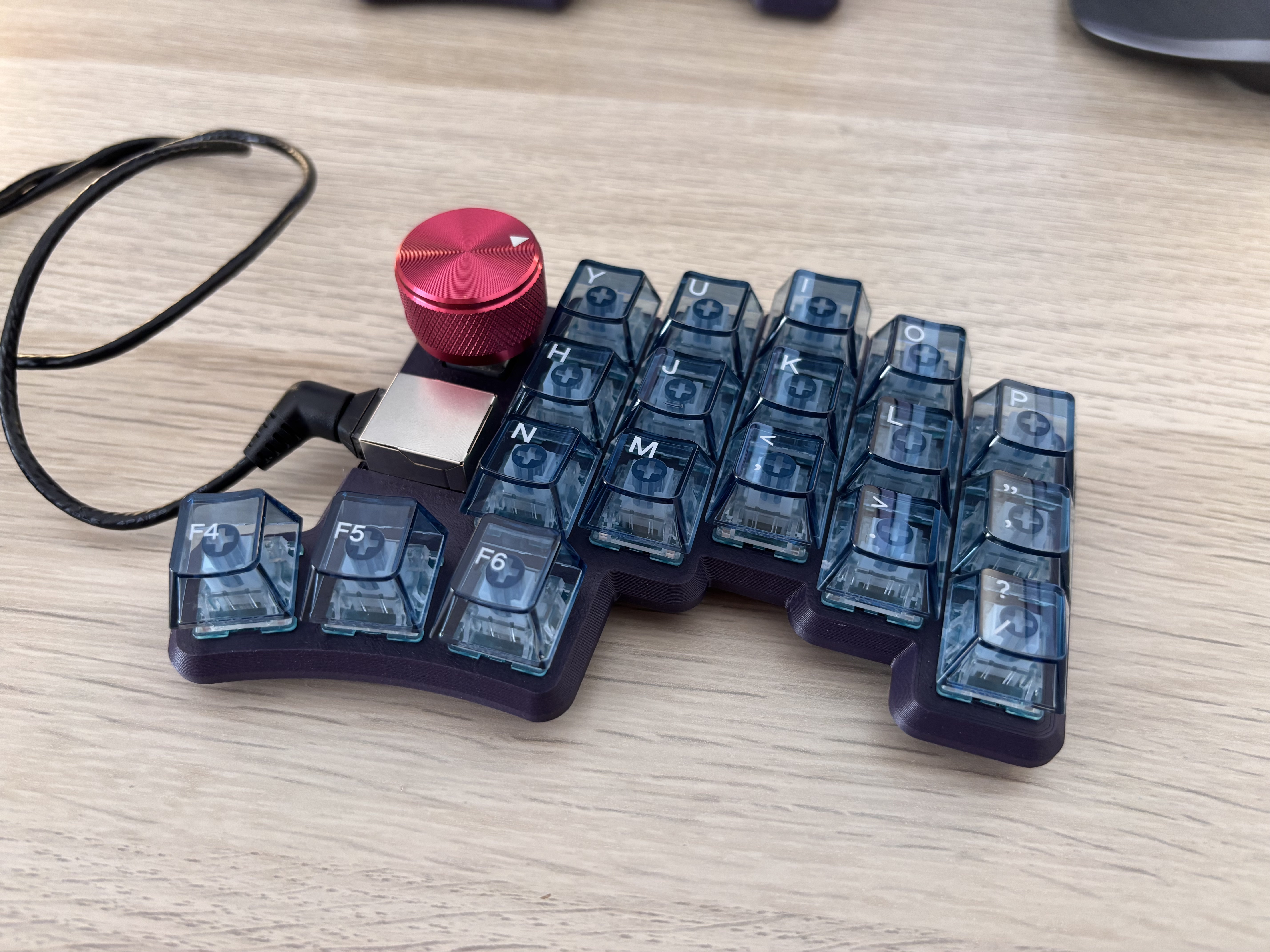
On JLCPCB you need to order a minimum of 5 PCBs and my friend helped me a lot through the build. I wanted to build him one of the keyboards. I ordered some tactile clicky switches, also from Outemu, and some clear keycaps with a blue hue on them.
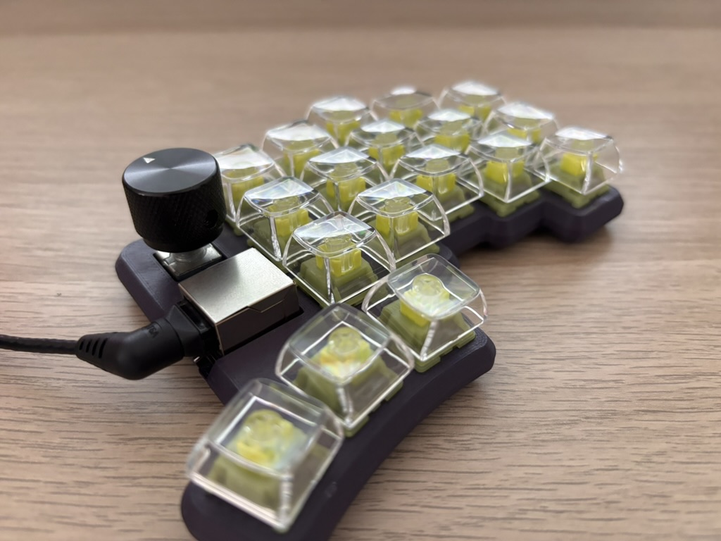
I think this build looks amazing too—especially with the red dial acting as an accent colour.
Here they are side by side. I love how this turned out, and I’m loving the experience of using a 35-key keyboard with a split design. It took me 2 weeks to get to at least 60 words per minute, and three more weeks before I could retire my old keyboard. This was a really nice experience overall and I feel really proud to use a keyboard I’ve built myself. Whether you’re unsure about it or simply looking for your next LEGO project, don’t hesitate. This is way better than LEGO (maybe even cheaper).
P.S.: For the layout nerds out there, I configured everything through the Vial Web interface until I wanted to copy my layout to the other keyboard. I’m still using QWERTY, but that may change: my left hand currently does far more work than my right and that feels weird.